The previous tip showcased a command that is available in Civil 3D that lets you find the closest distance between 2 objects and even draws a line at the closest points.
Here is a LISP routine that lets you do the same thing without having Civil 3D.
The LISP routine is found at the swamp.org and is by Joe Burke, Charles Alan Butler and VovKa.
Here’s How:
- Load the LISP file.
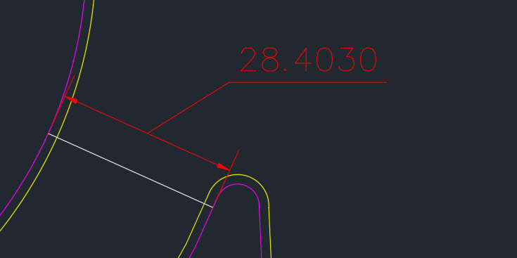
- In the command line use MD to select the 2 objects. The routine will show the minimum distance in the command line.
- If you would like for there to be a line drawn that shows the minimum distance, enter MDL in the command line and a line will be drawn that shows the closest distance.
~enjoy

;; http://www.theswamp.org/index.php?topic=23170.60
;; By Joe Burke, Charles Alan Butler and VovKa at theswamp.
;; Bug reports may be sent to me (Joe Burke) directly at
;; lowercase@hawaii.rr.com
;; Version 1.0 - 5/28/2008.
;; Find the minimum distance between two vlax-curve objects.
;; Supported object types: line, circle, arc, ellipse, polyline and spline.
;; Shortcut: MD
;; Notes version 1.0:
;; If two lines are parallel they are reported as such.
;; If the Z values of the two points found are not equal,
;; report at command line Z1 = x Z2 = x. When the objects
;; are not coplanar, the apparent minimum distance will
;; usually differ from the actual minimum distance.
;; There's an option to add a line on the current layer
;; drawn between the two closest points.
;; The object types selected are reported at the command line.
;; Version history:
;; Version 1.2 beta - 5/31/2008
;; Added the MinDistLine routine. Shortcut: MDL.
;; Allows the user to place a line between the last two closest points
;; calculated by MinDist after it ends. This avoids having to choose
;; whether a line is placed within MinDist itself. The idea is MinDist
;; is primarily a measuring tool. As such a minimum distance line is
;; rarely needed. Note, If the line drawn by MDL is off-screen it is
;; selected, otherwise not.
;; Version 1.3 beta - 6/8/2008
;; Added support for nested objects in blocks and xrefs.
;; Added MD:GetXrefs, MD:GetObject, MD:UnlockLayers, MD:RelockLayers
;; and MD:XMark sub-functions.
;; The first object selected is highlighted until the the second
;; object is selected similar to the fillet tool. If the first object
;; is contained in an xref it is not highlighted. Rather a temporary
;; X mark is placed where the object was selected to indicate the
;; the object is contained in an xref.
;; Version 1.4 beta - 6/10/2008
;; Added error checking for non-uniformly scaled blocks.
;; Version 1.4a - 6/21/2008
;; Bug fix for 2D (heavy) and 3D polylines.
;; Bug fix to avoid error if a dimension is selected.
;; Revised report when the Z values of the two points are not the same.
;; Version 1.5 beta - 6/30/2008
;; Added support for object types point, ray and xline.
;; If a ray or xline is involved the search for closest point along its
;; length is limited by the current view. The search extends beyond the
;; limits of the current view by a factor of approximately two both ways.
;; Version 1.5a beta - 7/1/2008
;; Fixed a bug with rays and xlines.
;; Both MD and MDL now report when both closest points are off screen.
;; Revised the MDL routine so it will not draw a very short or zero
;; length line. Added report for this case.
;; Added miscellaneous error checking.
;; Version 1.5b beta - 7/2/2008
;; Enter at select object prompt ends the routine.
;; Revised the UniformScale sub-routine to allow operation with objects
;; nested in dimensions. Thanks to Steve Doman.
;; Version 1.5c beta - 7/14/2008
;; Revised the fuzz factor in the MD:UniformScale function.
;; Version 1.5d - 8/24/2008
;; Added vla-StartUndoMark and vla-EndUndoMark. An undo after the
;; routine would restore a copied object.
;; Added function MinDistMove (MDM). Moves a selection set from
;; the first MinDist point to the second. The first object selected
;; within MinDist is the first point.
;; Version 1.5e - 9/6/2008
;; Fixed a minor bug which effected the MinDistMove function when
;; a ray or xline is involved.
;; Version 1.5f - 10/1/2008
;; Added Copy version of move. Shourtcut MDC.
;; Both MinDist and MinDistLine use the following two functions.
;; Returns the coordinates of the current view, lower left and upper right.
;; Works in a rotated view. Returns a list of two 2D UCS points.
(defun MD:GetScreenCoords ( / ViwCen ViwDim ViwSiz VptMin VptMax)
(setq ViwSiz (/ (getvar "VIEWSIZE") 2.0)
ViwCen (getvar "VIEWCTR")
ViwDim (list
(* ViwSiz (apply '/ (getvar "SCREENSIZE")))
ViwSiz
)
VptMin (mapcar '- ViwCen ViwDim)
VptMax (mapcar '+ ViwCen ViwDim)
)
(list VptMin VptMax)
) ;end
;; Arguments:
;; p1 - WCS or UCS point which defines the first corner of area
;; p2 - WCS or UCS point which defines the second corner of area
;; pt - point translated to UCS.
;; Returns: T if pt falls within area.
(defun MD:PointInside (p1 p2 pt / xval yval)
(and
pt
(setq pt (trans pt 0 1)
xval (car pt)
yval (cadr pt)
)
(< (min (car p1) (car p2)) xval (max (car p1) (car p2)))
(< (min (cadr p1) (cadr p2)) yval (max (cadr p1) (cadr p2)))
)
) ;end
(defun c:MinDist ( / *error* doc blocks units obj1 obj2 typ1 typ2 pkpt p2 sc
div fuzz d bd len inc idx resdist dellst res1 res2 pts
locklst interflag z1 z2 diff temp reverseflag
MD:Wait MD:NormalAngle MD:ParallelObjects MD:Pick
MD:GetXrefs MD:UnlockLayers MD:RelockLayers MD:GetObject
MD:XMark MD:UniformScale MD:XlineOrRay)
;; global vars: *mdp1* and *mdpt*
(vl-load-com)
(defun *error* (msg)
(cond
((not msg))
((wcmatch (strcase msg) "*QUIT*,*CANCEL*"))
(T (princ (strcat "\nError: " msg)))
)
(setvar "lunits" units)
(if
(and
obj1
(not (vlax-erased-p obj1))
)
(vla-highlight obj1 acFalse)
)
;; Objects may be switched when a ray or xline
;; is involved.
(if
(and
obj2
(not (vlax-erased-p obj2))
)
(vla-highlight obj2 acFalse)
)
(MD:Wait 0.2)
(redraw)
(foreach x dellst (vla-delete x))
(MD:RelockLayers locklst)
(vla-EndUndoMark doc)
(princ)
) ;end error
;;; START SUB-FUNCTIONS ;;;
;; Unlock locked layers.
;; Argument: document object.
;; Returns a list of layer objects which were locked,
;; or nil if none are locked.
;; Typically the function filters out xref layers,
;; but not in this case.
(defun MD:UnlockLayers (doc / laylst)
(vlax-for x (vla-get-Layers doc)
(if (eq :vlax-true (vla-get-lock x))
(progn
(setq laylst (cons x laylst))
(vla-put-lock x :vlax-false)
)
)
)
laylst
) ;end
;; Argument: a list of layer objects from UnlockLayers above.
;; Use vl-catch-all-apply in case a locked
;; layer was deleted in the calling function.
(defun MD:RelockLayers (lst)
(foreach x lst
(vl-catch-all-apply 'vla-put-lock (list x :vlax-true))
)
) ;end
(defun MD:GetXrefs (blklst / lst)
(if (vl-every '(lambda (x) (= (type x) 'ENAME)) blklst)
(foreach blk (mapcar 'vlax-ename->vla-object blklst)
(if (vlax-property-available-p blk 'Path)
(setq lst (cons blk lst))
)
)
)
(reverse lst)
) ;end
(defun MD:Wait (seconds / stop)
(setq stop (+ (getvar "DATE") (/ seconds 86400.0)))
(while (> stop (getvar "DATE"))
(princ)
)
) ;end
;; Argument: angle in radians, any number including negative.
;; Returns: normalized angle in radians between zero and (* pi 2)
(defun MD:NormalAngle (a)
(if (numberp a)
(angtof (angtos a 0 14) 0))
) ;end
;; Returns T if two lines, rays or xlines are parallel.
(defun MD:ParallelObjects (obj1 obj2 fuzz / ang1 ang2)
(if (eq "AcDbLine" (vlax-get obj1 'ObjectName))
(setq ang1 (MD:NormalAngle (vlax-get obj1 'Angle)))
(setq ang1 (MD:NormalAngle
(angle (vlax-get obj1 'BasePoint) (vlax-get obj1 'SecondPoint)))
)
)
(if (eq "AcDbLine" (vlax-get obj2 'ObjectName))
(setq ang2 (MD:NormalAngle (vlax-get obj2 'Angle)))
(setq ang2 (MD:NormalAngle
(angle (vlax-get obj2 'BasePoint) (vlax-get obj2 'SecondPoint)))
)
)
(or
(equal ang1 ang2 fuzz)
(equal ang1 (MD:NormalAngle (+ pi ang2)) fuzz)
(equal ang2 (MD:NormalAngle (+ pi ang1)) fuzz)
(equal (MD:NormalAngle (+ pi ang1)) (MD:NormalAngle (+ pi ang2)) fuzz)
)
) ;end
(defun MD:Pick (msg / typlst e obj typ scflag)
(setq typlst '("AcDbLine" "AcDbArc" "AcDbCircle" "AcDbEllipse"
"AcDbPolyline" "AcDb2dPolyline" "AcDb2dVertex"
"AcDb3dPolyline" "AcDb3dPolylineVertex" "AcDbSpline"
"AcDbRay" "AcDbXline" "AcDbPoint"))
(setvar "errno" 0)
(while
(or
(not (setq e (nentselp msg)))
(not (setq obj (vlax-ename->vla-object (car e))))
(not (vl-position (setq typ (vlax-get obj 'ObjectName)) typlst))
(and
(cadddr e)
(not (apply 'and (mapcar 'MD:UniformScale (last e))))
(setq scflag T)
)
)
(cond
((= 52 (getvar "errno"))
(exit)
)
((not e)
(princ "\nMissed pick. ")
)
(scflag
(princ "\nNon-uniformly scaled block detected, try again. ")
(setq scflag nil)
)
(typ
(princ (strcat "\n " (substr typ 5) " selected, try again. "))
(setq typ nil)
)
)
)
(if
(or
(eq "AcDb2dVertex" typ)
(eq "AcDb3dPolylineVertex" typ)
)
(setq obj (vlax-ename->vla-object (cdr (assoc 330 (entget (car e)))))
typ (vlax-get obj 'ObjectName)
)
)
;; Used to mark xref. Point passed to MD:XMark.
;; The variable is local in the main routine.
(setq pkpt (cadr e))
(if (= 2 (length e))
(list obj typ)
(list obj typ (caddr e) (cadddr e))
)
) ;end
;; Argument: UCS point.
;; Returns: nil
(defun MD:XMark (pt / len p1 p2 p3 p4)
(setq len (/ (getvar "viewsize") 75.0)
p1 (polar pt (* pi 0.3) len)
p2 (polar pt (* pi 0.7) len)
p3 (polar pt (* pi 1.3) len)
p4 (polar pt (* pi 1.7) len)
)
(grdraw p1 p3 7)
(grdraw p2 p4 7)
) ;end
;; Test for uniformly scaled block reference.
(defun MD:UniformScale (obj / x y z)
(if (= (type obj) 'ENAME)
(setq obj (vlax-ename->vla-object obj))
)
;; Added 7/2/2008.
(if (wcmatch (vlax-get obj 'ObjectName) "*Dimension")
T
(progn
(setq x (vlax-get obj 'XScaleFactor)
y (vlax-get obj 'YScaleFactor)
z (vlax-get obj 'ZScaleFactor)
)
(and
(equal (abs x) (abs y) 1e-12)
(equal (abs y) (abs z) 1e-12)
)
)
)
) ;end
;; Argument: a list returned by MD:Pick.
;; Returns: a vla-object. The first object in list if the object is
;; not nested. Otherwise a transformed copy of the object.
(defun MD:GetObject (lst / blkref blk obj)
(cond
;; Object is not nested.
((= 2 (length lst))
(setq obj (car lst))
)
;; Object is nested in an xref. Copy it within the xref database.
;; The owner is not specified within the CopyObjects function.
((setq blkref (car (MD:GetXrefs (last lst))))
(setq blk (vla-item blocks (vlax-get blkref 'Name)))
(setq obj
(car
(vlax-invoke
(vlax-get blk 'XRefDatabase) 'CopyObjects (list (car lst)))))
(vla-transformby obj (vlax-tmatrix (caddr lst)))
(setq dellst (cons obj dellst))
;; Grdraw X mark on xref where it was selected
;; if it is the first object selected.
(if (not obj1) (MD:XMark pkpt))
)
;; Object is nested in a block reference.
;; Copy it from the block and highlight in the main
;; routine if it is the first object selected.
(T
(setq obj
(car (vlax-invoke doc 'CopyObjects (list (car lst))
(vlax-get (vla-get-ActiveLayout doc) 'Block))))
(vla-transformby obj (vlax-tmatrix (caddr lst)))
(setq dellst (cons obj dellst))
)
)
obj
) ;end
;; Argument: ray or xline vla-object.
;; Returns: a list of two 3D WCS points beyond where the object
;; intersects the edges of the current view.
;; The base point of a ray may be returned depending on its
;; location relative to the view.
;; Revised 6/30/2008.
(defun MD:XlineOrRay (obj / basept zval secpt lst p pts p2 d typ
expt1 expt2 MD:RectanglePts MD:RectangleList
MD:FarthestPoint)
;;;; Sub-functions...
;; Pass two points representing a diagonal.
;; Returns a list of four UCS points.
(defun MD:RectanglePts (p1 p2)
(list
p1
(list (car p2) (cadr p1) (caddr p1)) ; revised 6/27/2008
p2
(list (car p1) (cadr p2) (caddr p2)) ; should be OK within context, testing
)
) ;end
(defun MD:RectangleList ( p1 p2 / rpts)
(setq rpts (MD:RectanglePts p1 p2))
(mapcar '(lambda (a b) (list a b)) rpts (append (cdr rpts) (list (car rpts))))
) ;end
(defun MD:FarthestPoint (pt ptlst / x dist res)
(setq x 0)
(foreach p ptlst
(setq dist (distance p pt))
(if (> dist x)
(setq x dist res p)
)
)
res
) ;end
;;;; End Sub-functions
(setq basept (trans (vlax-get obj 'BasePoint) 0 1)
zval (caddr basept)
secpt (trans (vlax-get obj 'SecondPoint) 0 1)
typ (vlax-get obj 'ObjectName)
)
;; two 2D UCS points
(if (not sc)
(setq sc (MD:GetScreenCoords))
)
(setq d (distance (car sc) (cadr sc))
sc (mapcar '(lambda (x) (append x (list zval))) sc)
lst (MD:RectangleList (car sc) (cadr sc))
sc nil
)
(foreach x lst
(if
(and
(setq p (inters basept secpt (car x) (cadr x) nil))
(inters basept p (car x) (cadr x))
)
(setq pts (cons p pts))
)
)
(cond
((eq "AcDbXline" typ)
(setq expt1 (polar (cadr pts) (angle (cadr pts) (car pts)) (* 2 d))
expt2 (polar (car pts) (angle (car pts) (cadr pts)) (* 2 d))
pts (reverse (list expt1 expt2))
)
)
;; Revised 6/29/2008
((eq "AcDbRay" typ)
(setq expt1 (MD:FarthestPoint basept pts)
expt1 (polar expt1 (angle basept secpt) (* 2 d))
pts (list basept expt1)
)
;; If base point is far away attempt to get a closer point
;; by testing for param at point.
(setq expt2 (polar expt1 (angle secpt basept) (* 5 d)))
(if (vlax-curve-getParamAtPoint obj (trans expt2 1 0))
(setq pts (reverse (list expt2 expt1)))
)
)
)
;; Trans UCS points to WCS as needed.
(mapcar '(lambda (x) (trans x 1 0)) pts)
) ;end MD:XlineOrRay
;;; END SUB-FUNCTIONS ;;;
;;; START MAIN FUNCTION ;;;
(setq doc (vla-get-ActiveDocument (vlax-get-acad-object))
blocks (vla-get-Blocks doc)
locklst (MD:UnlockLayers doc)
units (getvar "lunits")
)
(vla-StartUndoMark doc)
(sssetfirst)
(princ "\nSelect line, circle, arc, ellipse, polyline, spline, point, ray or xline.")
(if
(and
(setq res1 (MD:Pick "\nFirst object: "))
(setq typ1 (cadr res1))
(princ (substr typ1 5))
(setq obj1 (MD:GetObject res1))
(not (vla-highlight obj1 acTrue))
;; Get the screen coordinates here in case
;; the user pans between select objects.
(if
(or
(eq "AcDbRay" typ1)
(eq "AcDbXline" typ1)
)
(setq sc (MD:GetScreenCoords))
T
)
(setq res2 (MD:Pick "\nSecond object: "))
(setq typ2 (cadr res2))
(princ (substr typ2 5))
(setq obj2 (MD:GetObject res2))
)
(progn
(cond
((equal obj1 obj2)
(princ "\n Same object selected twice. ")
(setq resdist 0.0
interflag T
)
)
((vlax-invoke obj1 'IntersectWith obj2 acExtendNone)
(princ "\n Objects intersect. ")
(setq resdist 0.0
interflag T
)
)
((and
(eq typ1 "AcDbPoint")
(eq typ2 "AcDbPoint")
)
(setq *mdpt* (vlax-get obj1 'Coordinates)
*mdp1* (vlax-get obj2 'Coordinates)
d (distance *mdpt* *mdp1*)
)
)
((or
(eq typ1 "AcDbPoint")
(eq typ2 "AcDbPoint")
)
(if (eq typ1 "AcDbPoint")
(setq *mdpt* (vlax-get obj1 'Coordinates)
*mdp1* (vlax-curve-getClosestPointTo obj2 *mdpt*)
)
(setq *mdpt* (vlax-get obj2 'Coordinates)
*mdp1* (vlax-curve-getClosestPointTo obj1 *mdpt*)
)
)
(setq d (distance *mdpt* *mdp1*))
)
;; Core stuff follows.
(T
(if
(or
(eq typ2 "AcDbRay")
(eq typ2 "AcDbXline")
)
;; Reverse the objects and set a flag to reverse
;; the points later.
(setq temp obj1 obj1 obj2 obj2 temp reverseflag T)
)
(if (vlax-curve-getEndParam obj1)
(setq len (vlax-curve-getDistAtParam obj1 (vlax-curve-getEndParam obj1)))
;; Obj1 is an xline or ray.
(progn
(setq pts (MD:XlineOrRay obj1)
len (distance (car pts) (cadr pts))
idx1 (vlax-curve-getParamAtPoint obj1 (car pts))
idx2 (vlax-curve-getParamAtPoint obj1 (cadr pts))
)
(if (< idx1 idx2)
(setq idx idx1)
(setq idx idx2)
)
)
)
(if (not idx) (setq idx 0))
;; Number of divisions seems more than sufficient.
(setq div 200
inc (/ len div)
fuzz 1e-8
)
;; Check first object for the closest point on second object.
(setq bd
(distance
(setq *mdp1* (vlax-curve-getPointAtDist obj1 idx))
(vlax-curve-getClosestPointTo obj2 *mdp1*)
)
)
(repeat (1+ div)
(if
(and
(setq *mdp1* (vlax-curve-getPointAtDist obj1 idx))
(setq p2 (vlax-curve-getClosestPointTo obj2 *mdp1*))
)
(progn
(setq d (distance *mdp1* p2))
(setq idx (+ idx inc))
(if (<= d bd)
(setq bd d *mdpt* *mdp1*)
)
)
)
)
;; Refine the minimum distance as needed. Start with closest
;; point on first object. Bounce the closest points back and
;; forth between the two objects until delta distance is less
;; than the fuzz factor.
(while
(not
(minusp
(- (distance *mdpt*
(setq *mdp1* (vlax-curve-GetClosestPointTo obj2 *mdpt*)))
(setq d
(distance *mdp1*
(setq *mdpt* (vlax-curve-GetClosestPointTo obj1 *mdp1*))))
fuzz
)
)
)
)
)
) ;cond
(if (and d *mdpt* *mdp1*)
(progn
(setq resdist d)
;; Added 9/6/2008.
;; If objects were reversed, reverse the points.
(if reverseflag
(setq temp *mdpt* *mdpt* *mdp1* *mdp1* temp)
)
(grdraw (trans *mdpt* 0 1) (trans *mdp1* 0 1) -7 1)
(if
(and
(or
(eq "AcDbLine" typ1)
(eq "AcDbXline" typ1)
(eq "AcDbRay" typ1)
)
(or
(eq "AcDbLine" typ2)
(eq "AcDbXline" typ2)
(eq "AcDbRay" typ2)
)
)
(if (MD:ParallelObjects obj1 obj2 1e-8)
(if (and (eq "AcDbLine" typ1) (eq "AcDbLine" typ2))
(princ "\n Lines are parallel. ")
(princ "\n Linear objects are parallel. ")
)
)
)
;; Check the Z values of the two closest points.
(setq z1 (caddr *mdpt*) z2 (caddr *mdp1*) diff (abs (- z1 z2)))
(cond
((equal z1 z2 1e-10))
;; Units are scientific, decimal or engineering.
((< units 4)
(princ
(strcat "\n Z values of the points differ by: "
(rtos diff units 10)
)
)
)
;; The maximum display accuracy of architectural or
;; fractional units is 0.00196. If diff is less,
;; change units to decimal.
((and
(> units 3)
(< diff 0.00196)
)
(princ
(strcat "\n Z values of the points differ by: "
(rtos diff (setvar "lunits" 2) 10)
)
)
(setvar "lunits" units)
)
;; Otherwise display diff in architectural or fractional units.
(T
(princ
(strcat "\n Z values of the points differ by: "
(rtos diff)
)
)
)
) ;cond
) ;progn
) ;if
) ;progn
) ;if
(if (and resdist *mdpt* *mdp1*)
(progn
(princ (strcat "\n Distance: " (rtos resdist)))
(if (not interflag)
(progn
(setq sc (MD:GetScreenCoords))
(if
(or
(MD:PointInside (car sc) (cadr sc) *mdpt*)
(MD:PointInside (car sc) (cadr sc) *mdp1*)
)
(princ " Enter MDL to place minimum distance line. ")
(princ " Off screen points. MDL to place minimum distance line.")
)
)
)
)
(princ "\n Could not calculate minimum distance. ")
)
(*error* nil)
) ;end MinDist
;shortcut
(defun c:MD () (c:MinDist))
;; Added 8/24/2008.
;; Allows a selection set to be moved from the first MinDist point to
;; the second MinDist point. So the order of object selection within
;; MinDist is important in terms of which way the selection set will move.
;; IOW, if the user anticipates using this function after MD, the first object
;; selected determines move from point. The second object selected is
;; the move to point.
(defun c:MinDistMove ( / *error* doc osm ss)
(defun *error* (msg)
(cond
((not msg))
((wcmatch (strcase msg) "*QUIT*,*CANCEL*"))
(T (princ (strcat "\nError: " msg)))
)
(setvar "osmode" osm)
(vla-EndUndoMark doc)
(princ)
) ;end error
(setq doc (vla-get-ActiveDocument (vlax-get-acad-object)))
(vla-StartUndoMark doc)
(setq osm (getvar "osmode"))
(if (and *mdpt* *mdp1* (setq ss (ssget)))
(progn
(setvar "osmode" 0)
;; Added trans 8/27/2008.
(command "._move" ss "" (trans *mdpt* 0 1) (trans *mdp1* 0 1))
)
(princ "\nNothing selected or minimum distance points not set. ")
)
(*error* nil)
) ;end
;shortcut
(defun c:MDM () (c:MinDistMove))
(defun c:MinDistCopy ( / *error* doc osm ss)
(defun *error* (msg)
(cond
((not msg))
((wcmatch (strcase msg) "*QUIT*,*CANCEL*"))
(T (princ (strcat "\nError: " msg)))
)
(setvar "osmode" osm)
(vla-EndUndoMark doc)
(princ)
) ;end error
(setq doc (vla-get-ActiveDocument (vlax-get-acad-object)))
(vla-StartUndoMark doc)
(setq osm (getvar "osmode"))
(if (and *mdpt* *mdp1* (setq ss (ssget)))
(progn
(setvar "osmode" 0)
;; Added trans 8/27/2008.
(command "._copy" ss "" (trans *mdpt* 0 1) (trans *mdp1* 0 1))
)
(princ "\nNothing selected or minimum distance points not set. ")
)
(*error* nil)
) ;end
;shortcut
(defun c:MDC () (c:MinDistCopy))
;; Revised 6/30/2008.
;; Draw minimum distance line on the current layer.
(defun c:MinDistLine ( / d sc ss)
(cond
((not (and *mdpt* *mdp1*))
(princ "\n Minimum distance points not found. Run MD and then MDL to draw line.")
)
((and
(setq d (distance *mdpt* *mdp1*))
;(print d) ;testing
(< d 1e-5)
)
(princ "\n Minimum distance points are too close together. ")
)
(T
(entmake
(list
'(0 . "LINE")
(cons 8 (getvar "clayer"))
(cons 10 *mdpt*)
(cons 11 *mdp1*)
)
)
(setq sc (MD:GetScreenCoords))
(if
(or
(MD:PointInside (car sc) (cadr sc) *mdpt*)
(MD:PointInside (car sc) (cadr sc) *mdp1*)
)
(princ "\n Minimum distance line placed. ")
(progn
(princ "\n Minimum distance line placed off screen and selected. ")
(sssetfirst nil (setq ss (ssget "L")))
)
)
)
)
(princ)
) ;end MinDistLine
;shortcut
(defun c:MDL () (c:MinDistLine))